Balancing valves are essential components in HVAC and hydronic systems, used to control and regulate fluid flow to achieve energy-efficient, consistent, and reliable performance. But many system designers and maintenance teams often ask: where exactly should a balancing valve be installed to ensure maximum performance?
Let’s dive deep into the answer, looking at industry practices, reasoning, and placement strategies, while optimizing for key search terms like balancing valve installation, HVAC balancing valve location, and hydronic system design.
What Is a Balancing Valve
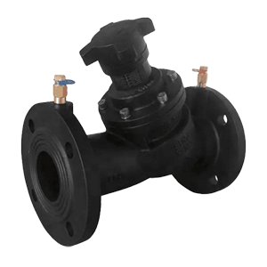
A balancing valve is a device used to regulate fluid flow in heating and cooling systems. It helps maintain proper flow rates, ensuring all parts of a building receive the right amount of thermal energy, whether it’s hot or chilled water. These valves are critical in avoiding problems like underheating, overheating, or inefficient energy usage.
There are two main types:
-
①Manual balancing valves (used for static systems)
-
②Automatic balancing valves (ideal for dynamic systems)
So, Where Should the Balancing Valve Be Installed
1. On the Return Side of the Terminal Unit (Preferred Position)
In most modern HVAC systems—especially those involving fan coil units (FCUs), air handling units (AHUs), or chilled beams—the balancing valve is installed on the return line, downstream of the coil or terminal unit.
Why?
-
①Accurate Flow Measurement: The return line provides a better representation of the total flow through the unit.
-
②Air Removal: It reduces the risk of trapping air in the system since air tends to accumulate in supply lines, and you don’t want it to get stuck near the measuring point.
-
③Flushing Advantage: Installing on the return line allows for easy system flushing from the supply to the return side.
2. At the End of Each Main Branch or Sub-circuit
In complex hydronic systems with multiple loops or zones, such as in multi-floor buildings or large commercial systems, balancing valves are installed at the end of each circuit to ensure:
-
①Even pressure distribution
-
②Proportional flow to each branch
-
③System-wide balance
This configuration is ideal for looped piping systems (e.g., reverse return or direct return systems).
3. Before or After Control Valves (Depending on Design)
In systems with pressure independent control valves (PICVs), balancing may be handled internally, and additional balancing valves may not be required at the terminal unit level. But in systems with two-way control valves and no PICVs, a balancing valve should still be placed after the coil and control valve, in the return line.
4. Pump Discharge Headers (For System Balancing)
For primary-secondary systems or variable primary flow systems, balancing valves may also be used:
-
①On pump discharge headers
-
②At bypass lines or decoupling points
This helps regulate differential pressure and stabilize system performance.
Installation Tips
-
①Use balancing valves with flow measurement ports to allow quick commissioning.
-
②Place valves in accessible locations for ongoing adjustment and maintenance.
-
③Consider temperature and pressure ratings suitable for your system’s specifications.
-
④Balance the system using specialized tools or digital flow meters for accuracy.
-
⑤Combine with differential pressure controllers or PICVs in dynamic flow systems.
Summary: Where to Install Balancing Valves
| Location | Purpose | Common in |
|---|---|---|
| Return side of coil | Accurate flow control & air removal | FCUs, AHUs, chilled beams |
| End of branch circuits | Proportional distribution | Multi-zone systems |
| Before/after control valve | Complements modulation | Static two-way valve systems |
| Pump headers | System-wide control | Central plant piping |
Post time: Aug-08-2025