DIN Standard StormValve
Product Description
Storm valve is a flap type non-return valve which is used to discharge the sewage overboard. It is connected to the soil pipe at one end and other end is at ships side so that sewage gets overboard. So it can be overhauled only during drydocks .
Inside the valve flap is there which is attached to a counter weight, and a locking block. The locking block is the piece of the valve that is controlled and operated by the external hand wheel or actuator. The purpose of the locking block is to hold the flap in place which ultimately prevents the flow of fluid.
Once flow begins, the operator must choose whether to open the locking block, or keep it closed. If the locking block is closed, the fluid will stay out of the valve. If the locking block is opened by the operator, fluid can flow freely through the flap. The pressure of the fluid will release the flap, allowing it to travel through the outlet in one direction. When flow stops, the flap will automatically return to its closed position.
Regardless of whether or not the locking block is in place, if flow comes through the outlet, the back flow will not be able to enter the valve due to the counterweight. This feature is identical to that of a check valve where back flow is prevented so that it will not contaminate the system. When the handle is lowered, the locking block will again secure the flap in its close position. The secured flap isolates the pipe for maintenance if necessary
Specification
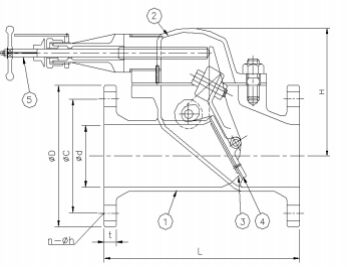
| Part No. | Material | ||||||
| 1 - Body | Cast Steel | ||||||
| 2 - Bonnet | Cast Steel | ||||||
| 3 - Stem | Brass | ||||||
| 4 - Plug | Brass | ||||||
| 5 - Nut | Steel, | ||||||
Product wireframe
Storm valve is a fap type non-return valve which is used to discharge the sewage overboard, it is connected to the sol pipeat one end and other end is at ships side so that sewage gets overboard. So it can be overhauled only during drydocks.
inside the valve flap is there which is attached to a counter weight, and a locking block. The locking block is the piece ofthevalve that is controlled and operated by the external hand wheel or actuator. The purpose of the locking block is to hold theflap in place which ultimately prevents the flow of fluid.
Once fow begins, the operator must choose whether to open the locking block, or keep it closed. lf the locking block isclosed, the fuid will stay out of the valve, lf the locking block is opened by the operator, luid can fow freelv through the flap.The pressure of the fiuid will release the flap, allowing it to travel through the outlet in one direction. When flow stops, the flapwill automatically return to its closed position.
Regardless of whether or not the locking block is in place, if fow comes through the outlet, the back fow will not be able toenter the valve due to the counterweight, This feature is identical to that of a check valve where back flow is prevented sothat it will not contaminate the system. When the handle is lowered, the locking block will again secure the flap in its closeposition.The secured flap isolates the pipe for maintenance if necessary.
Dimensions Data
| DN | n1×Φd1 | Hcd1 | ΦD1 | n2×Φd2 | Hcd2 | ΦD2 | ΦD | L1 | H1 | H2 | ΦR | Kg |
|---|---|---|---|---|---|---|---|---|---|---|---|---|
| 50 | 4×18 | 125 | 165 | 8×18 | 160 | 200 | 70 | 180 | 90 | 260 | 140 | 12 |
| 65 | 4×18 | 145 | 185 | 8×18 | 180 | 220 | 85 | 200 | 100 | 270 | 140 | 14 |
| 80 | 8×18 | 160 | 200 | 8×18 | 210 | 250 | 100 | 215 | 108 | 290 | 140 | 20 |
| 100 | 8×18 | 180 | 220 | 8×22 | 240 | 285 | 130 | 250 | 130 | 305 | 140 | 25 |
| 125 | 8×18 | 210 | 250 | 8×22 | 270 | 315 | 158 | 290 | 152 | 330 | 160 | 36 |
| 150 | 8×22 | 240 | 285 | 8×22 | 295 | 340 | 190 | 330 | 176 | 260 | 160 | 43 |
| 200 | 8×22 | 295 | 340 | 12×22 | 350 | 395 | 240 | 425 | 180 | 350 | 160 | 72 |